Provision and Launch Edge iNodes
- 04 Sep 2024
- 8 Minutes to read
-
Print
-
DarkLight
Provision and Launch Edge iNodes
- Updated on 04 Sep 2024
- 8 Minutes to read
-
Print
-
DarkLight
Article summary
Did you find this summary helpful?
Thank you for your feedback
This article explains how to provision and launch Edge iNodes (physical hardware).
To begin the process, log in to your company account:
- Type <yourcompany>.secureedge.view.com into your browser, replacing <yourcompany> with your company’s name.
- Enter the Secure Edge login and password that we gave you for your account.
- Select Login.
To get your Edge iNodes up and running, complete the following procedures to install the hardware device you received from us and connect it to the network.
If you’re planning to use Virtual LANs (VLANs), see also Enabling VLANs for an Organization.
Set up Edge iNode Physical Network Connections
Note
You can configure iNode networks before physically connecting the iNode to the network.
As a prerequisite for Edge iNode operation, the iNode needs to be connected to the network. One Ethernet port is always reserved for WAN connectivity. This port should be connected to an available network that has internet access. Refer to Prerequisites for iNode Connectivity for more information about the requirements for this internet connection.
The remaining port(s) are available for connecting to LAN networks. These LAN networks are onboarded to support the following activities:
- Protection using the iNode’s firewall functionality.
- Remotely accessing devices via Remote Access Portal.
- Running services and applications.
- Facilitating cloud connectivity through secure tunnels.
Depending on the model of iNode you have, there are between two and four ethernet ports available. To can reference the available ports, you can view the port diagram directly in the portal. To view the hardware diagram, navigate to the iNode’s Details page and select the iNode name listed next to Vendor.
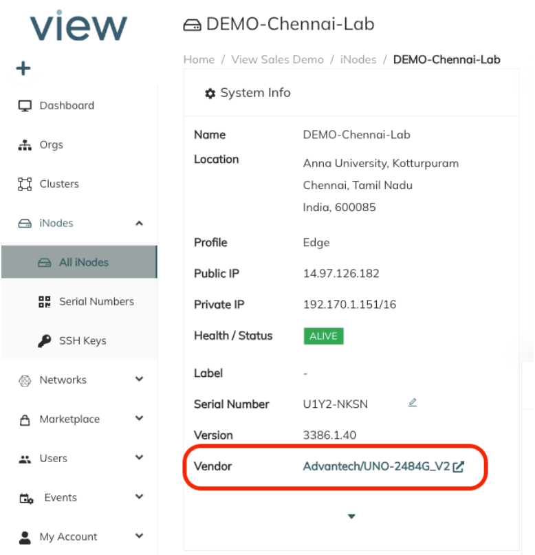 The Hardware Diagram will appear.
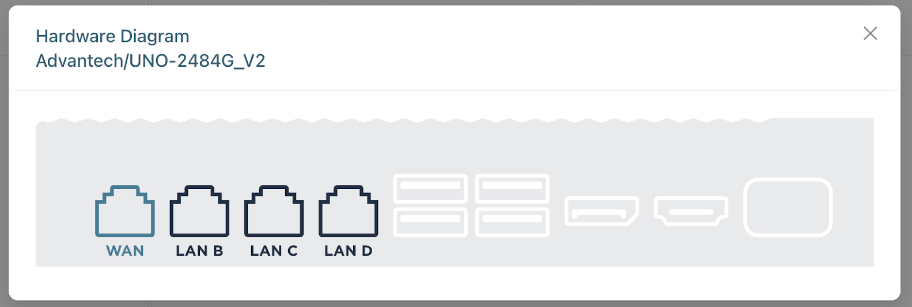
By default, on Model 2484 iNodes, LAN A and LAN B are the only active ports. To enable the other ports, refer to Advanced Network Interface Configuration on Edge iNodes.
The labels shown in the diagram match the labels printed on the physical iNode device. These labels are used throughout the portal to maintain consistency.
Connect the port designated as WAN to the appropriate network to establish internet connectivity. Connect the other ports as necessary to facilitate connection into the appropriate LAN networks.
If you have a converged network, the LAN port(s) on the iNode support VLAN segmentation. For more information on enabling and configuring VLANs on the iNode, refer to Using VLANs on Edge iNodes.
Provisioning Edge iNodes
Set up Edge iNodes using the Secure Edge Portal to add them as a network element, assign them to local networks, and add attributes.
Before you start, make sure you have an SSH public key to use for access authentication of the Edge iNode console. For more on SSH key management, see Managing SSH Key Authentication for an iNode.
Add an Edge iNode
To add a new Edge iNode, follow these steps:
- To add an iNode, in the Secure Edge Portal left menu, select the plus icon (+) > Add iNode.
- Enter the iNode name.
- Optionally, you can also specify custom attributes as Label. (For more on labels, see Using Labels.)
- Select the Edge profile.
- We’ve pre-populated the hardware serial numbers in Secure Edge Portal for the hardware devices that we shipped to you. Select the Serial Number that matches the serial number label on your hardware device.
- For SSH Key, select the name of the SSH public key for use when logging into the console of this iNode. (If you don’t have an SSH public key to use, see Managing SSH Key Authentication for an iNode.)
- Next, add location information for the iNode (street address, city, state/province, zip/postal code). Based on these geolocation values, your iNodes will appear on a map in the Dashboard landing page.
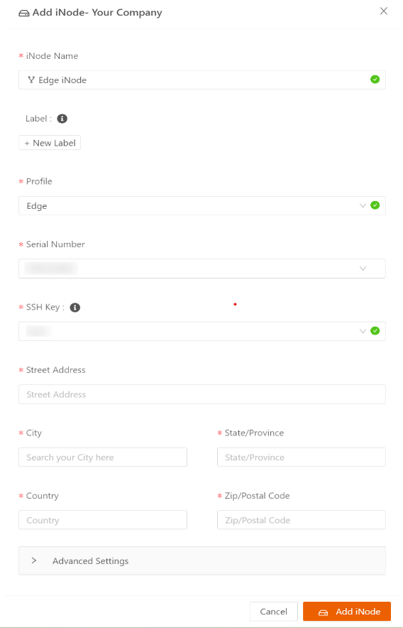
- You can change the Data Saving Mode in Advanced Settings. (For more on data saving mode, see Using Data Saving Mode.)
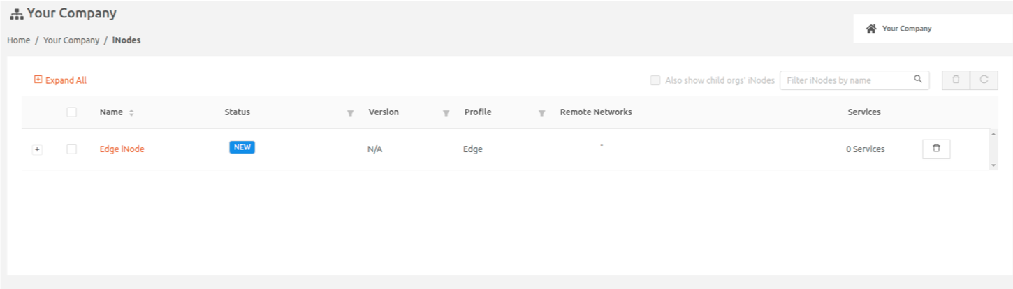
- Select Add iNode to add the new iNode to the iNodes page.
Add the Local Network to Be Protected by this Edge iNode
Note regarding duplicate network CIDRs
Two networks on the same iNode can support the same subnet. In the case this is required, the use of Representational Networking shall be used when assigning Remote Networks for each network.
If two networks are added to the same iNode with the same subnet, the iNode is not actively checking for network loops. It is the responsibility of the installer to ensure that the networks are properly segmented.
If two networks are added to the same iNode with the same subnet, the iNode is not actively checking for network loops. It is the responsibility of the installer to ensure that the networks are properly segmented.
- Select the name of the newly added iNode to display the iNode details page.
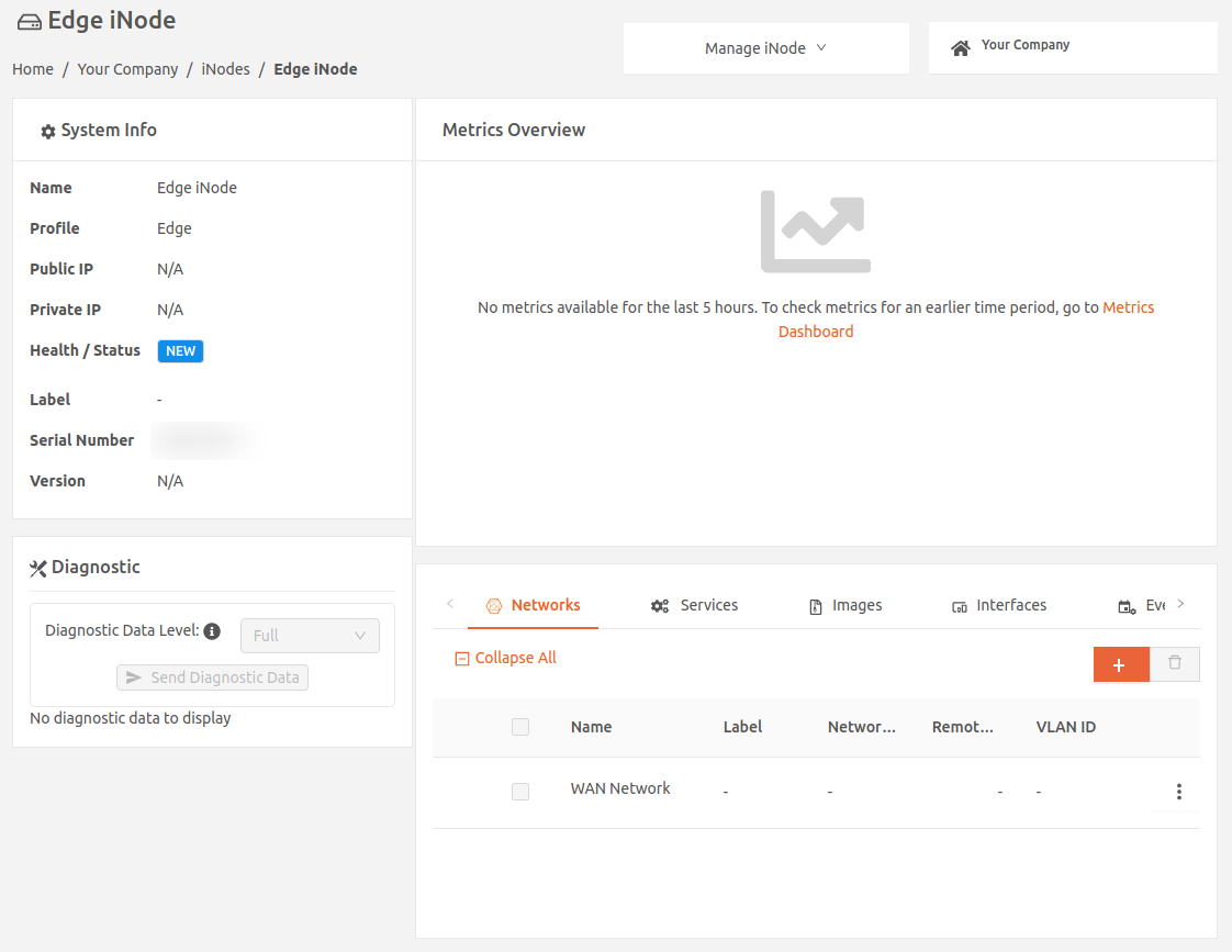
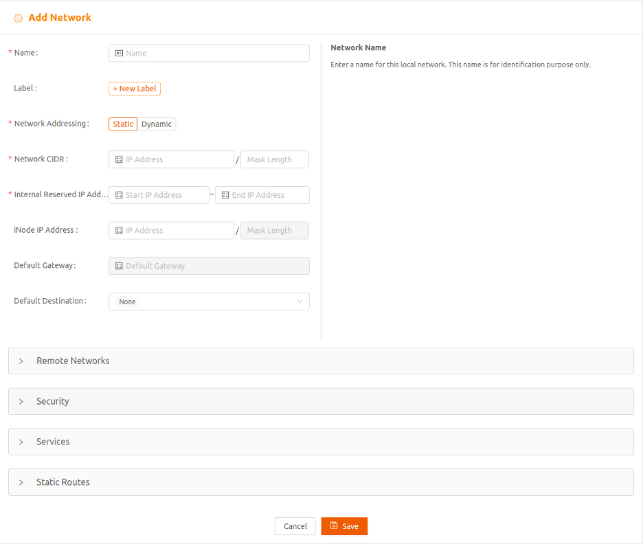
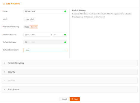
- To specify the local network that will be protected by this iNode, select the plus icon (+) to display the Add Network page. Enter the network name in the Name field, and optionally, specify any custom attribute as a Label. (For more on labels, see Using Labels.)
Set Up Static Network Addressing
You can set up either static or dynamic network addressing for the iNode.
- To set up static network addressing, in which the hosts in the network must be manually configured with static IP addresses, follow the steps in this section.
- To create a dynamic local network for the iNode, in which a Dynamic Host Configuration Protocol (DHCP) server provides and manages IP addresses, skip to the section Set Up Dynamic Network Addressing.
Follow these steps to create a static local network:
- If the Networking Addressing for this network is to be Static, the hosts in this network must be manually configured with static IP addresses. Select Static for Network Addressing.
- Specify the network's CIDR in the Network CIDR field.
- Specify a range of IP addresses (at least one) that will be reserved for iNode internal use. These IP addresses must be part of the same IP subnet as the local network's CIDR.
- Specify the IP address of the iNode interface on this network in iNode IP Address. This is an optional field. If you don’t set it, the start IP address configured in the previous step will be the IP address for the iNode and the default gateway for devices on this network. If you set iNode IP Address, it will be the default gateway.

- If you plan to use services on this iNode, you need to set up IP addressing for services you plan to run. By default, the iNode assigns IP addresses for services dynamically from the Internal Reserved IP Address Range you specified. If you’re using the default, make sure you’ve reserved enough IP addresses. You need at least one more than the number of services you plan to run.
- If you plan to configure the services manually with static IP addresses, select the Services expansion panel and set Service Addressing to Static.
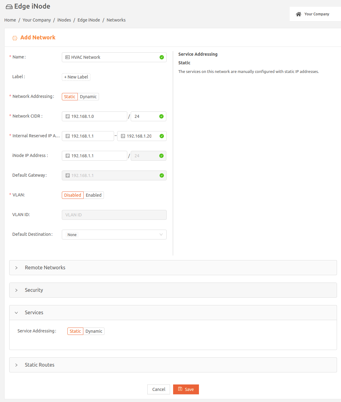
- Select Save and continue with the section Complete Network Setup.
Set Up Dynamic Network Addressing
You can set up either static or dynamic network addressing for the iNode.
- To create a dynamic local network for the iNode, in which a DHCP server provides and manages IP addresses, follow the steps in this section.
- To set up static network addressing, in which the hosts in the network must be manually configured with static IP addresses, go back to Set Up Static Network Addressing.
Follow these steps to create a dynamic local network:
- If the Networking Addressing for this network is to be Dynamic, a DHCP server provides and manages its IP addresses. Select Dynamic for Network Addressing.
- Specify the IP address of the iNode interface on this network in iNode IP Address. This will be the default gateway for devices on this network.
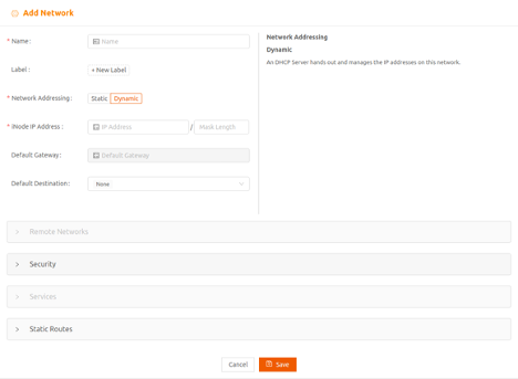
- If you plan to run services on the iNode, when you select dynamic network addressing, by default, a DHCP server assigns IP addresses to services on the network and the Services panel is disabled. You may, however, configure static IP address for the the core services, Kea DHCP, PowerDNS, Postgres, and NTP when you add the services to your iNode. (Refer Edge Services.)
- Select Save and continue with the section Complete Network Setup.
Complete Network Setup
Follow these steps steps to complete the local network setup:
- You may have the option of configuring Virtual LANs (VLANs). (For more on VLANs, see Using VLANs on Edge iNodes.)
- Any traffic from the local network with a destination outside the local network (for example, traffic going to the internet or LAN) is sent to the default destination. You can set the Default Destination to one of the following:
- None (default), which results in dropping the traffic
- Specify IP Address, which sends the traffic to the IP address of a gateway in the local network that you specify
- WAN Network, which sends the traffic through the iNode uplink
- Select Save.
Create Static Routes for an Edge iNode
Create static routes if you want:
- Services running on the Edge iNode to reach specific routed network segments behind the iNode
- Hosts in the local network to reach specific networks in your LAN or the internet
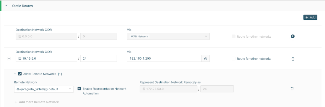
- Select the Static Routes expansion panel and select Add to add a new static route. You can add up to 64 static routes per network. Note that if you set Default Destination to a value other than None, it uses up a static route.
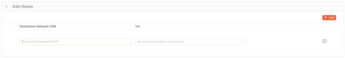
- Specify the CIDR of the destination network in the Destination Network CIDR field.
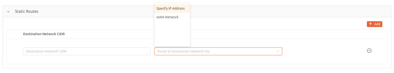
- Select where to send the traffic going to the destination network in the Viafield. Select one of the following:
- Specify IP Address, which sends the traffic to the IP address of a gateway in the local network that you specify
- WAN Network, which sends the traffic through the iNode uplink
- If you need devices on this segmented network to be accessible via Remote Access or other Virtual iNodes, select the Allow Remote Networks checkbox
- In the expanded section, select the remote network you would like to map the segmented network to.
- You can also specify a Representational Network value or select Enable Representation Network Automation to assign the NAT for you.
- You can add 25 remote networks per route.
- Select Save.
Launching an Edge iNode
To launch an Edge iNode, follow these steps:
- Power-on the iNode hardware device. The Edge iNode automatically discovers the uplink network through DHCP and securely connects to Secure Edge Portal in the cloud.
- If you want to configure the uplink interface to use static IP, please refer to Appendix A.
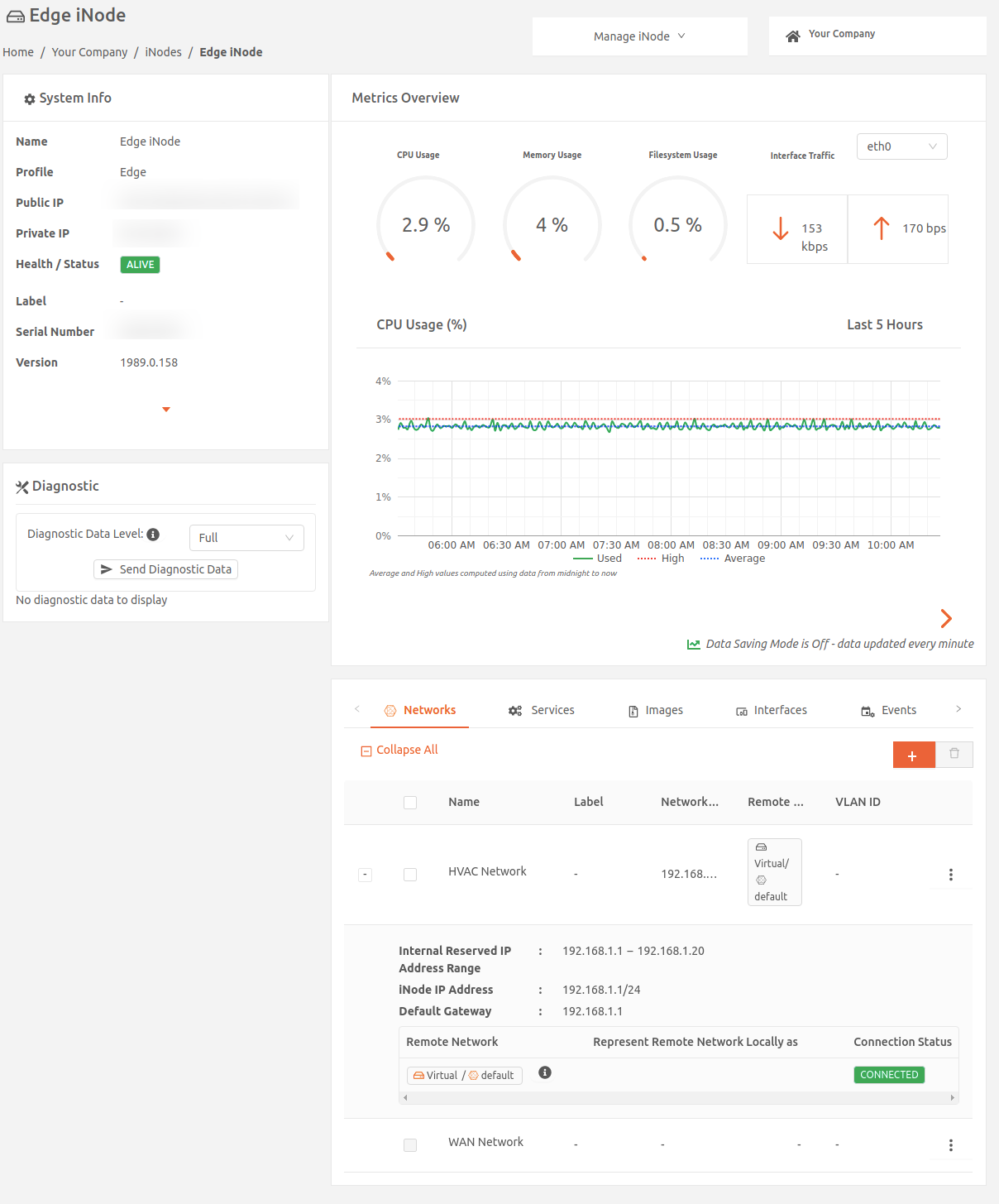
- To make sure the Edge iNode was successfully provisioned, log in to Secure Edge Portal to see whether the status is shown as ALIVE on the iNode Details page.
If you have a firewall between the iNode and the internet, make sure that outbound connections on TCP port 443 are not blocked by the firewall.
Managing Unassigned Serial Numbers
If you are a reseller, partner, or use child orgs within your environment, you can manage unassigned serial number iNodes. When an iNode is provisioned by View, the serial number is assigned to your environment and listed on the Serial Numbers page. Admins in Secure Edge can move these unassigned serial numbers into child orgs associated with the parent organization.
Follow these steps to move an unassigned serial number into a child org.
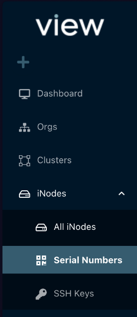
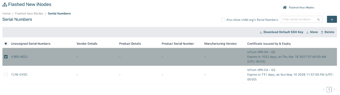
- From the Secure Edge left menu under iNode, select Serial Numbers.
- Select the Serial Number you want to move and then, from the top-right menu, select Move.
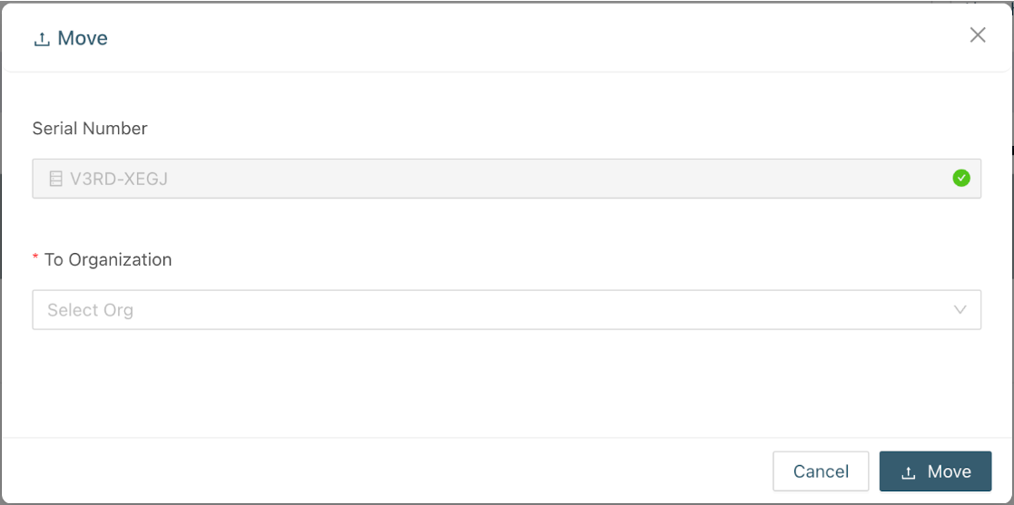
- In the To Organization drop-down field, select which Child Org you would like to move the iNode to.
Was this article helpful?